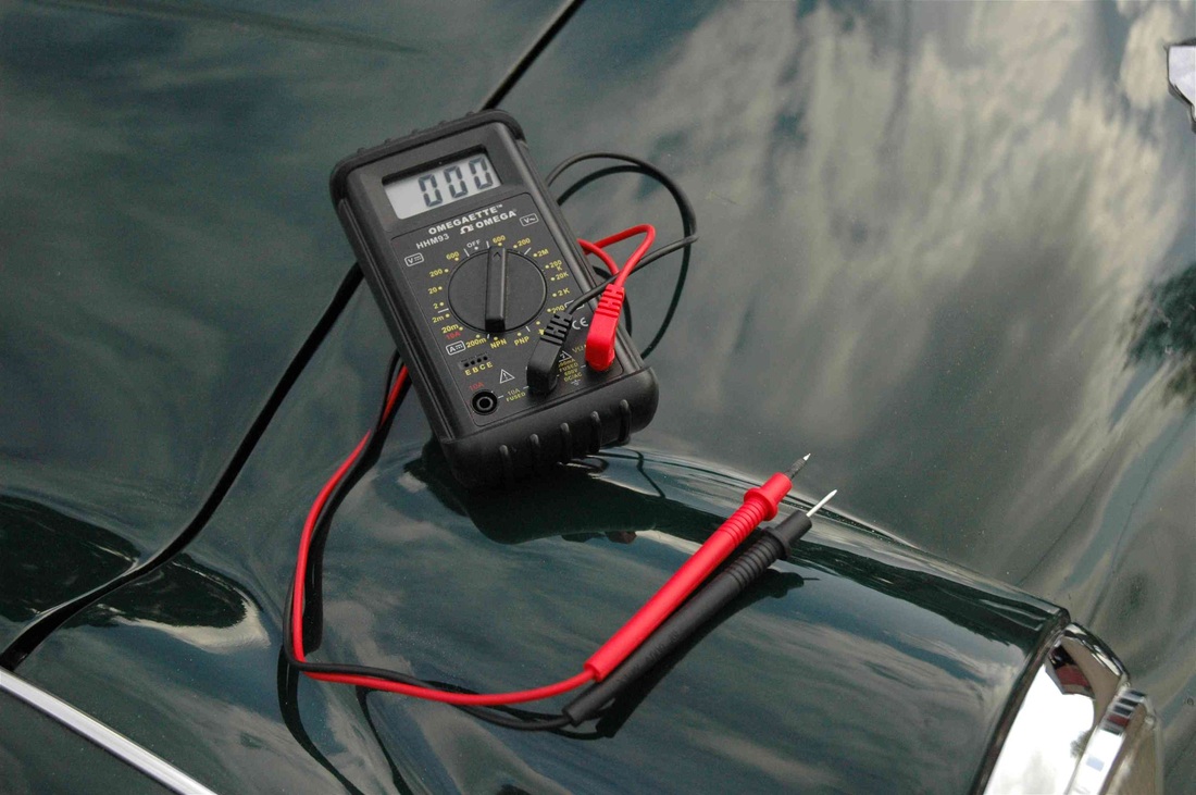
Using a Multimeter to fault find on Classic and older cars
This information was originally published as an article in TRaction the club magazine of the Triumph TR Register and although biassed towards the sidescreen Triumph TR's hopefully it will be useful to owners of other marques.
This information has been gathered from personal experience and is believed to be accurate but there is no guarantee that this is the case. Anyone using this information does so on the understanding that its use is completely at their own risk and that no legal liability of any kind will be accepted by the author for errors or ommisions or consequential damage to persons or possessions. Prospective users should make their own considered judgement or seek specialist advice as to the accuracy or otherwise of any statements made before using this information in any way.
This information has been gathered from personal experience and is believed to be accurate but there is no guarantee that this is the case. Anyone using this information does so on the understanding that its use is completely at their own risk and that no legal liability of any kind will be accepted by the author for errors or ommisions or consequential damage to persons or possessions. Prospective users should make their own considered judgement or seek specialist advice as to the accuracy or otherwise of any statements made before using this information in any way.
A little knowledge is a dangerous thing ! This is especially true with electricity, as without a great deal of care it can cause untold damage to both person and possessions. Automobile electrics are however rather more forgiving and while without care you may damage some car components you are unlikely to kill yourself .
Electricity is unseen so we need instruments to indicate its presence the "Multimeter "is one of these. Wheras multimeters were once expensive and the domain of electronics/electrical specialists who understood the capabilities and limitations of these devices they are now inexpensive and commonplace but unfortunately not all users understand them. Hopefully the following will go some way to improve matters so that enthusiasts will be able to use a multimeter more effectively. In my experience many people are confused between Current measured in Amps and Voltage (or Potential Difference) measured in Volts. To make any sense of electrical measurement it is vital that these two are understood.
Before an electric current can flow, we need something for it to flow through e.g. a piece of wire, termed a conductor. We also need something to drive the current through the conductor that is a voltage across its ends. What does this mean in practice. Well as electricity is invisible we can use a water analogy to explain: In Figure 1 the tank of water feeds a vertical tube with taps at the levels h , 2h and 3h. Each tap is the same size. If tap A is opened the water spurts out to distance d from the tube, if tap B is opened water now reaches distance 2d and likewise for tap C the water reaches to 3d.
|
|
Figure 1 Figure2
As can be seen the higher the head of water the greater distance the water spurts out. It is exactly the same with electricity. If the head of water is now replaced with batteries as in Figure 2 a single battery cause current I amps to flow, doubling the voltage by having two batteries in series causes 2 x I amps to flow and likewise 3 batteries in series causes a current of 3 x I Amps. Returning to the water analogy if we now imagine a domestic central heating system. If a ground floor radiator develops a pin hole leak the water will spray out in a narrow jet as the pressure of water forces it out. If however in trying to stem the flow we inadvertently pull a feed pipe out of the radiator (in addition to the loud blast in your ear from your loved one) the water gushes out in abundance as there is now a much bigger hole and thus much less resistance to water flow. In exactly the same way any conductor will have a certain resistance to current flow, this could be a copper wire or perhaps a plastic clothes line. If the terminals of a car battery are shorted out with some copper cable there will probably be a loud crack and the cable will most likely burn out and you may damage your battery -Dont try it. If the experiment is now repeated with a plastic line there will not even be a spark. This is because the plastic clothes line has a very high resistance to current flow wheras the copper cable has a very low resistance. A long time ago Mr Ohm discovered that there was a very simple relationship between current flow, voltage and this resistance:
I (current in Amps) = V (potential difference in Volts) Divided by R (Resistance in Ohms).
i.e. I =V/R
If we substitute typical values for a 12 volt car battery, a yard of thinish cable could have a resistance of 1/10 of an ohm and the plastic line about 10 Million ohms . If we return to Ohms equation of I = V/R So for the cable I = 12/0.1 i.e 120 Amps ( a large current) but For the clothes line I = 12/10,000000 i.e. 1.2 Micro amps (1.2/1,000000) a barely measurable amount. This is the basis of all measurements with a multimeter, understand this and you are half way there.
For an electric current ( I) to flow through any conductor of resistance (R) there must be a driving force or potential difference (V) across it. The current flowing, I =V/R. Simples!
Multimeters can measure voltage and current , voltage and current may be Direct as from a car battery or Alternating as from the mains supply. They also measure resistance. For Classic cars such as the TR the vast majority of measurements will be either of DC Voltage or Resistance.
An initial warning, with all multi-meter measurements when measuring Resistance ensure that all Voltage supplies are switched off , if not the measurements will be affected and you could destroy the meter. Always disconnect the vehicle battery before making resistance measurements.
Before Looking at some typical electrical faults familiarize yourself with your meter. Try measuring the dc voltage across your car battery, and try various smaller torch type batteries so as to get used to measuring. You should also study your meter instructions to understand its capabilities:
Select the Resistance (Ohms) range on your meter and short circuit the two measuring probes together, the meter should read zero 0 ohms. Try and measure your own resistance. Holding the meter probes in each hand a fairly high reading of around 50,000 ohms or 50 K-ohms is typical, the value depends on how thick skinned you are! This is one good reason when measuring resistance for keeping hands away from the metal probe ends to avoid modifying the readings. Now wet your hands and repeat the measurement, you will find it much lower as water although a relatively poor conductor is better than skin. This is why electric shocks from the 240 volt ac house mains are much more serious in a bathroom or kitchen as the water lowers your resistance and causes much greater current to flow, frequently a lethal amount.
The 12 volt car battery by itself cannot give you an electric shock as its voltage is too low but its capacity to burn out cables etc. and harm you through burning if still a possibility as anyone who has experienced a vehicle electrical fire will testify. This is the reason that fuses are used for the various circuits and electrical devices. In the event of a fault condition (low resistance) that could cause a cable to burn, the fuse fails instead and protects the cable.
A reminder of Ohms law: I=V/R as R is reduced so I increases
Next try measuring the resistance of some car bulbs. Three typical 12 Volt automobile bulbs as shown here:
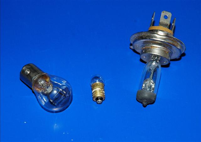
The 12 Volt 21/5 Watt rear side/brake lamp bulb to the left, a typical Quartz Halogen Headlamp/Dipped beam bulb to the right rated at 12 volt 60/55 Watt and a 12 volt 2.2 Watt dashboard lamp in the centre. We will deal with "Watts" in more detail later for now just think of it as the Power of the bulb or its light output,
large Watts = bright light and vice versa.
The filaments of the headlamp/dipped beam bulb should have resistances of around 0.5 and 1.0 ohm, in other words a low value. If it measures a high value then the bulb has blown. Similarly the 21/5 Watt bulb filaments should measure around 1.0 and 2.5 ohms. The much lower power dashboard lamp should measure around 7 ohms. If the resistance measures very much more than this then the filaments are probably open circuit. Some meters are rather inaccurate on the lower ohms ranges and may indicate zero ohms for all of the above. That is OK, only a high ohms reading indicates a failed filament. This is a quick and easy method of checking if car bulbs are serviceable.
Typical car electrical faults will now be looked at.
Caution: Modern vehicles use complex electronics to control a whole raft of electrical devices including such obscure things as monitoring whether the lights are functioning correctly. Do not attempt to follow the advice given below in tracing faults on these vehicles as the chance of causing very expensive damage is a distinct possibility. Fortunately original TR's are quite simple in comparison and you are most unlikely to cause any damage.
In the first article it was shown that for an electric current " I " in Amps to flow through a conductor of resistance " R" measured in Ohms we require a voltage or potential difference across the ends of a conductor " V " volts. And that according to Ohms law: I = V/R
So that if we are able to measure two of these quantities then the third can easily be calculated. A multimeter allows this to be acheived. In tracing electrical faults on classic cars the two quantities most often measured are DC Voltage and Resistance.
Moving on to a typical fault likely to be found on TRs.
Fault 1: Dip headlamp on the nearside not working but main beam ok and off-side lights all ok. Initially we need to look at the circuit diagram, using the TR2 diagram below as an example:
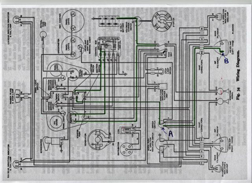
Triumph TR2 Circuit Diagram Scanned from the TR2 Service Manual
Before measuring anything, with a bit of logical investigation it is possible to narrow the fault down to a few parts of the circuit. The relevant wiring to the nearside dip lamp is highlighted in green:
1.The wiring to both dip headlamps are taken from a common terminal on the dip switch (dipper switch) so the dip switch is obviously working otherwise the off side dip would also have failed.
2. Likewise the -12 volt feed to the dipswitch must be present as without it neither dip nor main beam bulbs would be illuminating.
3. So the fault must lie between "A" and "B" i.e. somewhere between the dipswitch terminal and the nearside dip lamp bulb.
We can now narrow the fault even further by measuring the resistance of the dip/main lamp bulb, remove it from its socket, clean its terminals and check for a low resistance on both filaments. A high (greater than a few ohms) measurement would indicate a blown dip filament. Assuming the dip filament checks ok we can move back to the car and make a DC voltage measurement. Note, that unlike moderns original sidescreen cars were wired with a Positive earth. With the meter on an appropriate DC volts range, switch on the dip beams and carefully measure the voltage at the nearside dip/main beam bulb socket. With the positive meter lead (Red) to the earth side of the socket measure the dip and main beam terminals in turn (with the Black probe), be careful not to short circuit the meter probes otherwise you may see some sparks and melt your probes. The main beam terminal should read -12 volts (as it was working ok) the dip probably zero or less than -12 volts. Check for corrosion, switch off the lamps and clean the socket and lamp bulb as necessary. If the dip beam socket terminal now measures -12 volts, the fault has been located.
Corrosion of lamp sockets is very common. ( if your car has been converted to Negative earth, reverse the polarities above).
If the fault persists, now identify the nearside dip beam connection on the dip switch and with dip beams switched on, measure the voltage with the positive meter lead earthed (battery +ve is fine), it should measure -12 volts, if not the teminal will most likely be corroded, clean it up and remeasure. With -12 volts on the dip switch terminal but zero or low volts still on the dip lamp socket the fault must lie in the wiring between these points i.e. between A and B or more likely within a connector in the circuit.
Bullet Connectors
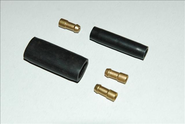
Bullet connectors are used extensively in the side screen cars and are
notoriously unreliable and liable to corrosion. With the battery disconnected and
the meter on a resistance range measure the resistance from the dip switch
terminal "A" to the dip beam lamp socket terminal "B", it should measure a
fraction of an ohm, anything higher indicates a faulty connection. Trace the
cable route and check and clean any connectors in the circuit and look
particularly for corroded bullet type connectors. Bearing in mind the age of
the cars the connectors may have been changed to a more modern plug/socket but
could even be just bare wires twisted together and insulated. Wires and or
connectors may need resoldering.
Copper wire that has been in service for a while will most likely be oxidised to give a black appearance, even under its insulation. The wire must be cleaned back to a bright copper colour with fine emery cloth otherwise it will not solder effectively. When the resistance from A to B is a fraction of an ohm, and with -12 volts at the dip beam terminal and a good main/dip lamp bulb plugged in there is now no reason why the lamp should not operate. It is possible for the wiring itself to fail within the insulation but in my experience unless there has been some abrasion or overloading etc. This is most unlikely.
So by a logical sequence of tracing the circuit, measuring voltage and resistance the fault has been identified. This same sequence may be used to fault find almost any electrical fault on a TR, summarising
- From the circuit identify the relevant wiring /components and pin point the likely culprits
- Using the meter measuring resistance and or dc voltage to drill down even further
- Clean or replace corroded connectors and terminals resoldering if necessary
- Identify the fault
What is a Watt? Earlier, three common car bulbs were shown with various power ratings ranging from the dashboard bulb at 2.2 Watt to the head lamp main beam filament at 55 Watt. So what is a watt? A Watt defines the rate that work is expended or put another way the rate of energy conversion. For a car bulb it measures the amount of energy used by the bulb, not the light output. The light output will depend on how efficient the
bulb is at converting electrical energy into light. 1 Watt is defined as the power expended when 1 volt causes a current of 1 Amp to flow through a circuit. This brings us to a useful formula:
W=I xV or Watts = Amps x Volts.
So knowing the power of say a bulb e.g. 55 Watts and if used on a normal 12 volt circuit we can easily calculate the current flowing:
W = I x V therefore I = W/V and in our example I = 55/12 , i.e. 4.58 Amps.
So why is this useful? Well in the above example knowing the power of a bulb we can easily calculate the current drawn and thus the thickness of cable required. It is usual to allow some margin of safety, so for the headlamp bulb, cable rated at 10 amps maximimum, should be adequate.
Why do car batteries or indeed any batteries eventually fail? Well, above, when a simplified circuit of a battery driving current around a loop was shown some elements were initially omitted, this diagram is more complete:
Any circuit even a loop of wire will have some resistance ("r2 and r3" left) this needs to be added. All batteries also have some resistance even if this is very low. This is represented by "r1" in the diagram. When a car battery is new and fully charged its internal resistance
r1 will be very low, a fraction of an ohm.
To start a 2 litre engine on a cold day when the oil is thick can take a very large current. If we assume that the starter motor ( R) has a resistance of 0.1 ohm* and the batteries resistance r1 is 0.01 ohm then from Mr Ohms law:
I = V/Rtotal , i.e. I = V/R+r1 i.e I = 12/ 0.11 = 109 amps
If the battery becomes discharged r1 could rise say to 0.2 ohm, recalculating:
I =12/0.3 i.e. 40 amps , a large current but maybe not enough to turn the cold engine.
Additionally , in the cicuit we omitted the resistance of the leads from the battery to the starter motor and the main battery earth lead represented by "r2 and r3". So a truer value of current flowing I is: V / (R +r1 +r2 +r3)
So if either of these leads has a corroded contact it could easily represent a resistance of 0.2 ohm, or more, enough to cause the car to fail to start.
While on the subject of circuit resistance, why is it that the 240 volt ac domestic supply is very capable of killing you wheras the much higher 20,000 volts of the ignition HT feeding the spark plugs seldom causes much beyond a shock. Well again all down to the internal resistances* "r" of the supplies. For the ac mains "r" is very low and not a limiting factor wheras for the ignition HT circuit* "r" is very high so cannot sustain a high enough current to cause harm.
A typical ignition low tension (LT) circuit will be passing about 1 Amp through the contact breaker and the ignition coil primary.
So the power expended by the LT side is 12 x 1 = 12 Watts
Now the high tension (HT) side of the ignition coil generates about 20,000 volts. As the HT power out has to be less than the LT power in (due to heat losses in the coil) if we assume 2 Watts is lost as heat we are left with 10 watts to fire the spark plugs.
Now from above I = W/V, so the current flowing is 10/20,000 = 0.5 millli amps
*And the effective resistance of the coil secondary R = V/I, i.e. 20,000/0.5 = 40,000 Ohms
This is the reason that the inclusion of a radio suppressor or a high resistance suppressing ignition lead each with a resistance around 5,000 ohms , makes little difference to the quality of the spark.
*With the ac mains supply, motors and in fact ignition coils although internal resistances have been mentioned, internal impedance would be the more correct term. With an alternating supply, coils and transformers are involved and other factors termed inductance and capacitance have to be considered along with resistance that gives rise to Impedance, but this is beyond the scope of this article.
Warning: Some electronic ignition circuits are capable of delivering a much greater shock that could harm someone with a weak heart etc.
A bit off the subject, but a good way to test ordinary torch batteries NOT CAR BATTERIES.
A normal AA battery has a voltage of about 1.5 volts, 1.3 volts if a rechargeable cell. So with the meter on dc volts first measure the voltage. If this is low then the cell is definitely discharged. If it measures OK it may still be unservicable because a meter on its voltage range takes a negligable amount of current and does not test the battery under normal working conditions. The batteries internal resistance may have risen to prevent it delivering sufficient current to be useful in service.
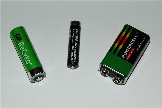
AA, AAA Rechargeable cells and a PP9 Battery
Select the high DCamps range on your meter and momentarily short circuit the torch battery, I mean extremely quickly to avoid discharging the cell. A fully charged: AA cell should give between 5 -10 amps .
An AAA cell between 3-8 amps
And a 9 volt PP9 cell about 3 amps
This is an extreme test and maybe frowned upon by some but I have used it successfully for over 30 years to decide whether a torch cell is servicable. It is also about the only time I use the meter to measure DC current directly.
Earlier the basic relationshipbetween Voltage(V), Current(I) and Resistance(R) was shown to be:
I = V / R, i.e. Amps = Volts / Ohms
And that Power W =V x I, i.e. Watts = Volts x Amps
Tracing electrical faults can be rather daunting to many but by using a logical approach there is no reason why most electrical faults on a TR cannot be identified or at least narrowed down. Although specific examples will be explained it is the method of diagnosis that is important not the specific faults described.
A fuse Blowing
A fairly common fault in older cars is a fuse blowing, sometimes the fuse itself can be faulty so changing it cures the fault but much more frequently it means that something is overloading the circuit and changing the fuse merely causes it to blow again. The Circuit Diagram below has been kindly supplied by Autowire www.advanceautowire.com
A fairly common fault in older cars is a fuse blowing, sometimes the fuse itself can be faulty so changing it cures the fault but much more frequently it means that something is overloading the circuit and changing the fuse merely causes it to blow again. The Circuit Diagram below has been kindly supplied by Autowire www.advanceautowire.com
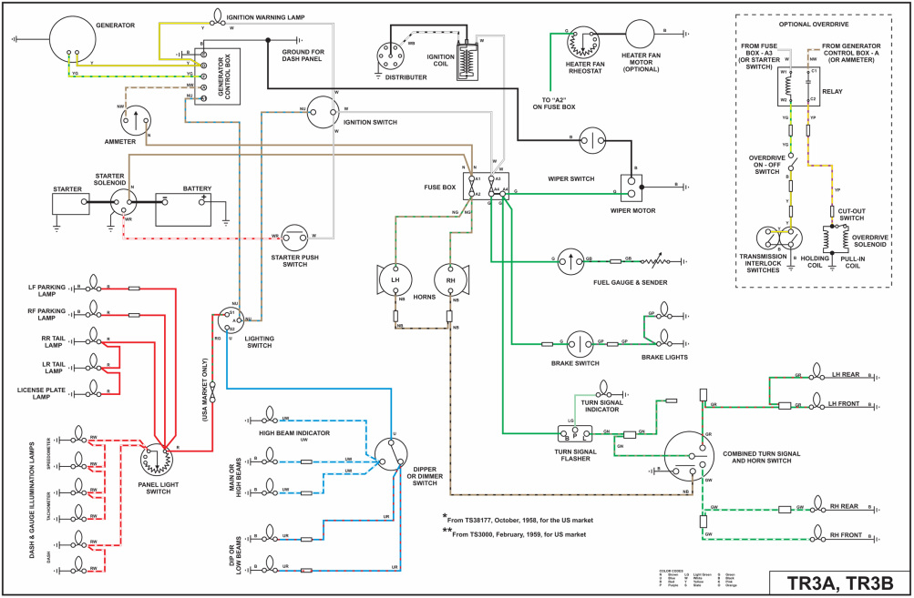
This shows the layout and components very much clearer than the original factory diagram. The basic TR3A only has two fuses as shown, one between A1and A2 the other from A3 to A4. Unlike modern cars some circuits are not fused at all. The 3As circuits are powered thus:
- The main battery Positive is earthed to the chassis and engine, the battery negative (-VE) is initially wired to the starter motor. From there it connects to fuse A1 and the Ammeter.
- From the Ammeter it feeds terminal “A” on the control box.
- Inside the control box after passing through a few turns of a low resistance sensing coil it emerges at terminal “A1”, for practical purposes in this example “A” on the control box may be viewed as directly connected to “A1”.