TVR Griffith
This information has been gathered from personal experience and is believed to be accurate but there is no guarantee that this is the case. Anyone using this information does so on the understanding that its use is completely at their own risk and that no liability for errors or omisions or consequential damage to persons or possessions will be accepted by the author or his agents. Prospective users should make their own considered judgement or seek specialist advice as to the accuracy or otherwise of any statements made before using this information in anyway.
This information has been gathered from personal experience and is believed to be accurate but there is no guarantee that this is the case. Anyone using this information does so on the understanding that its use is completely at their own risk and that no liability for errors or omisions or consequential damage to persons or possessions will be accepted by the author or his agents. Prospective users should make their own considered judgement or seek specialist advice as to the accuracy or otherwise of any statements made before using this information in anyway.
Heater Problems
It seems to be a common problem with the heating system in the Griffith that it is impossible to turn off the heating completely, the warm or hot air that is continually blown into the cabin can make summer outings rather unbearable, this is certainly my experience. Heat regulation is achieved via a water valve in one of the heater matrix water pipes. The system uses an electric motor to move the valve, controlled by the top left hand heat knob on the heater panel. The position of the valve is tracked by a servo system that uses potentiometers (variable resistances) one attached to the motor spindle, the other to the heat control knob. When the heater knob is rotated a potential difference is applied to the motor and it drives the valve until the rotational position of the two potentiometers is the same, i.e. if the heat knob is rotated say from 12 o-clock to ten-past the motor will drive the valve until its potentiometer also reaches ten-past, at this point the potential difference is zero so the motor then stops. In the simplified illustration below both potentiometers are midway so that 6 volts is applied to both sides of the motor, the potential difference is thus zero and the motor is at rest with the valve half open.
It seems to be a common problem with the heating system in the Griffith that it is impossible to turn off the heating completely, the warm or hot air that is continually blown into the cabin can make summer outings rather unbearable, this is certainly my experience. Heat regulation is achieved via a water valve in one of the heater matrix water pipes. The system uses an electric motor to move the valve, controlled by the top left hand heat knob on the heater panel. The position of the valve is tracked by a servo system that uses potentiometers (variable resistances) one attached to the motor spindle, the other to the heat control knob. When the heater knob is rotated a potential difference is applied to the motor and it drives the valve until the rotational position of the two potentiometers is the same, i.e. if the heat knob is rotated say from 12 o-clock to ten-past the motor will drive the valve until its potentiometer also reaches ten-past, at this point the potential difference is zero so the motor then stops. In the simplified illustration below both potentiometers are midway so that 6 volts is applied to both sides of the motor, the potential difference is thus zero and the motor is at rest with the valve half open.
|
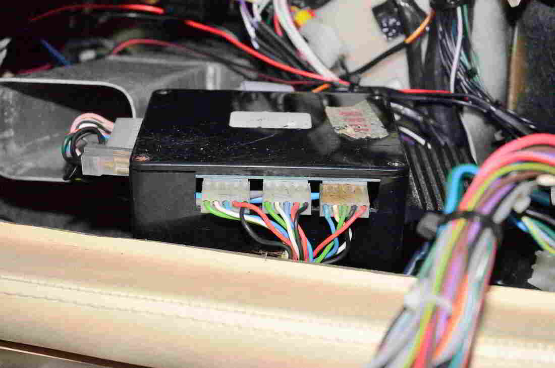
The Heater Servo Amplifier module
|
Diagram to illustrate the operation of the water valve servo (simplified)
There are three heater controls, one to control the amount of water entering the heater matrix ( i.e. as described above).
The second controls whether heated air is directed to the windscreen or to the cockpit and the third controls whether the heated air is fresh air from outside or recirculated cabin air. All three systems employ the sevo arrangement as shown in the simplified diagram. In practice the current supplied from the contol potentiometers alone is not sufficient to drive the servo motors so that amplifiers are introduced between the control panel and the servo motors. The amplifiers are contained within the Module shown above right. Connection between the control panel and the module is via a ribbon cable. Connections to the three servos is via three identical 5 way output plugs. As each servo is virtually identical if a fault is suspected then the output plugs may be cross plugged to fault find.
To Align The Water Valve Servo
A few pictures will hopefully explain the operation of the system. It is essential that when the heat control knob is at a minimum the valve is fully closed, this is frequently not the case. It is much easier to remove the valve to investigate.
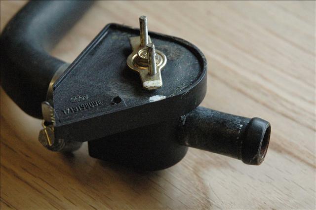
The water valve
The basic water valve with the motor detached is shown above, note the white paint marks on the movable arm and the valve body. When the arm is in this position the valve should be fully closed, this may be checked by blowing into the valve. The Servo motor with its reduction gearbox is seen below,the drive pulley is secured on the shaft with a Philips headed bolt and then fixed to the valve arm by two small bolts (seen on the water valve arm above).
The basic water valve with the motor detached is shown above, note the white paint marks on the movable arm and the valve body. When the arm is in this position the valve should be fully closed, this may be checked by blowing into the valve. The Servo motor with its reduction gearbox is seen below,the drive pulley is secured on the shaft with a Philips headed bolt and then fixed to the valve arm by two small bolts (seen on the water valve arm above).
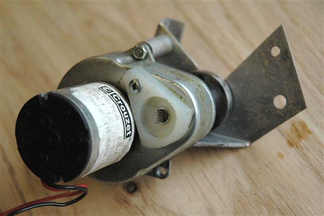
The Servo Motor and Gearbox
A rear view of the complete assembly is shown below with the extended motor shaft that drives the motor potentiometer
A rear view of the complete assembly is shown below with the extended motor shaft that drives the motor potentiometer
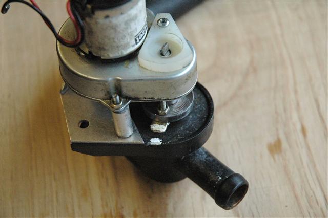
The Complete Valve Unit
The valve unit is fitted to the heater matrix rubber tube in the passengerfoot-well. The motor servo 10 K Ohm potentiometer can be seen hanging freely with its blue/green/white connecting wires.
The valve unit is fitted to the heater matrix rubber tube in the passengerfoot-well. The motor servo 10 K Ohm potentiometer can be seen hanging freely with its blue/green/white connecting wires.

The water valve fitted in the heater matrix water pipe
To Align:
1. Set the heater temperature control (top left knob) to minimum
2. Ensure the water valve is set to off, i.e. with the valve arm and valve body white marks coincident
3. Loosen the Philips-headed bolt securing the pulley to the motor shaft
4. Allow the motor potentiometer to hang free as in the illustration
5. Turn on the ignition and the motor should start running
6. Adjust the potentiometer with a small screw driver until the motor stops. Hopefully the white marks will still be coincident, so secure the pulley on the shaft and fit the potentiometer on the shaft end (just a push fit) making sure that the slot engages correctly on the shaft flat
7. Rotate the heater control knob throughout its travel and note that at maximum with the water valve fully open the valve arm has only rotated through about ¼ of a turn
8. Rotate the control back to minimum to check that the valve closes again with the white marks in line
The above sequence may have to be repeated a few times for accurate tracking.
The original potentiometers are now unavailable. In fact they are no longer manufactured. A close alternative will fit after a small modification.
The central solder lug needs to be bent close to the body of the potentiometer to allow the device to locate in the nylon moulding. The central hole that locates on the drive shaft of the motor is somewhat larger than the original at 3.3 x 4mm so is a rather sloppy fit on the 1.0 x 4mm shaft. It does seem to operate OK though. Although It is preferable to align the potentiomer with the valve disconnected from the water supply (as detailed above) it is possible to align things with the valve in situ. Method:
1. With the potentiometer disconnected from the valve assembly turn the heat control on the dash to minimum.
2. Turn on the ignition and the valve motor will run continuously
3. By adjusting the potentiometer with a screwdriver a point can be reached that stops the motor.
4. By observing the two white marks on the water valve it can be seen how far open or closed the valve now appears.
5. With small adjustments of the potentiometer the motor can be made to start or stop and turn clockwise or anticlockwise.
6. With careful adjustment the valve can be made to stop in the off position. This may take several attempts
7.Carefully place the potentiometer in the nylon moulding (without moving its electrical position) paying special attention to locate the drive shaft.
8. Turn the heater control on the dash to maximum and the valve should open if the potentiometer has been correctly set up.
9. If the potentiomer is thrown out of the moulding you have probably wired the blue and green connections back to front. So unsolder and reverse them.
This procedure takes a lot longer to try and explain than to carry out in practice but is successful if care is taken
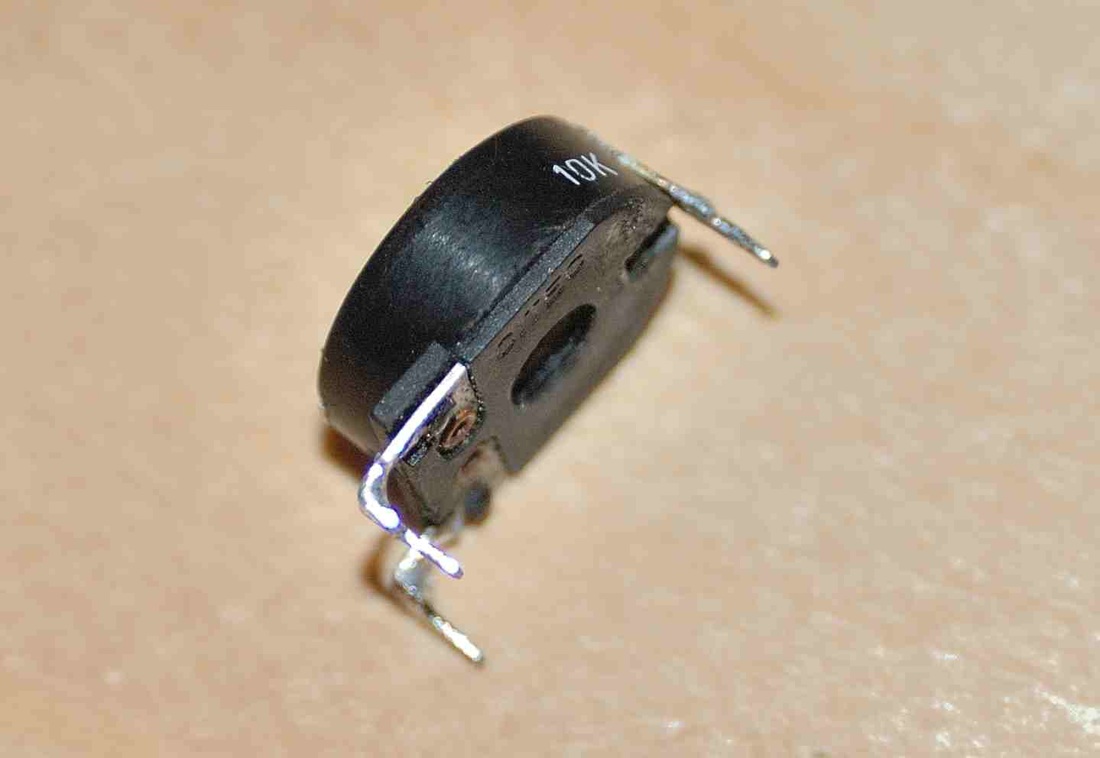
The Original Potentiometer
|
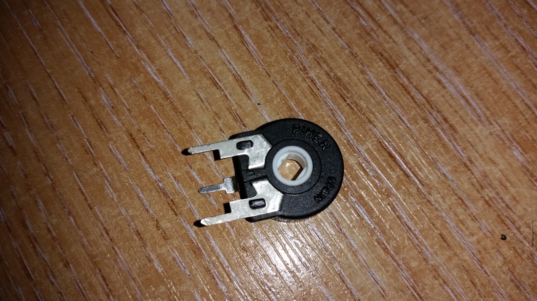
An Alternative Potentiometer
|
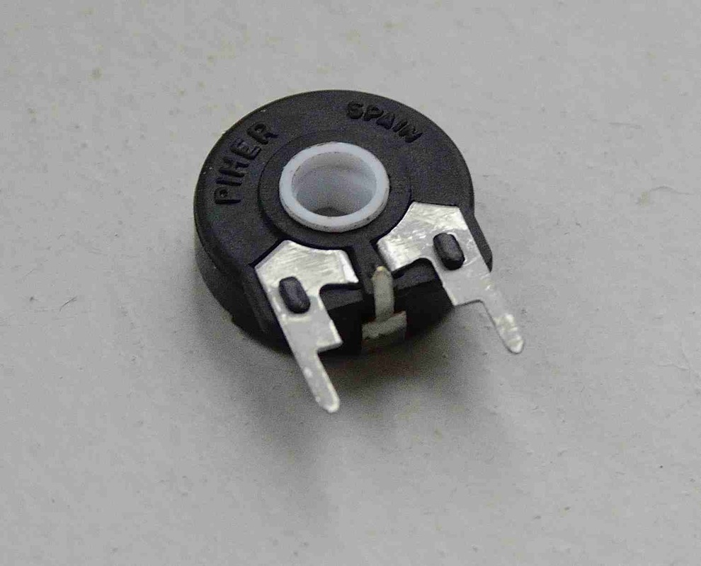 Altered central solder lug Altered central solder lug
|
Even with the water valve correctly aligned you may still find that the heater pumps out a fair amount of heat when at minimum. Some owners report cool air but most complain of uncontrolled warm air. Note: The above explanation is simplified as in practice the heater control unit HCU (electronic black box) is used to amplify the small current variations from the potentiometers to a level sufficient to drive the 12 volt motor. If the above does not fix your problem you could have a faulty HCU. Replacement is probably then the only solution. I found that even after careful alignment instead of permanent hot air, warm air was still circulated with the valve closed. It seems that despite the valve being closed heat still gets through to the matrix. As a test I made up a temporary blanking plug and inserted it into the heater supply tube from the inlet manifold under the ignition coil, the result was cool air even during a long trip.
Supplier: The potentiometers are now available from TVR Parts: http://tvr-parts.com
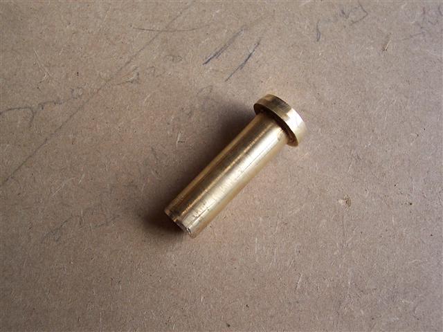
Heater Blanking Plug
Some early cars have a heater bypass arrangement so that water still circulates from the inlet manifold feed even if the electric valve has stopped the flow to the heater matrix. Steve Heath shows this in his Griffith/Chimera manual. Later cars do not have the bypass so with the electric heater valve off no water can circulate from the inlet manifold feed so fitting a manual in-line tap to these cars should not cause any problems. As a permanent solution a suitable heater tap was found at Europa the 16mm version fitted my (1996 Griffith 500) heater tubes. The ignition coil was unbolted to allow access and a section of tube was cut out to allow the tap to be inserted, the tap fits conveniently and neatly under the coil.
Supplier: The potentiometers are now available from TVR Parts: http://tvr-parts.com
Heater Blanking Plug
Some early cars have a heater bypass arrangement so that water still circulates from the inlet manifold feed even if the electric valve has stopped the flow to the heater matrix. Steve Heath shows this in his Griffith/Chimera manual. Later cars do not have the bypass so with the electric heater valve off no water can circulate from the inlet manifold feed so fitting a manual in-line tap to these cars should not cause any problems. As a permanent solution a suitable heater tap was found at Europa the 16mm version fitted my (1996 Griffith 500) heater tubes. The ignition coil was unbolted to allow access and a section of tube was cut out to allow the tap to be inserted, the tap fits conveniently and neatly under the coil.
|

|
It is now a simple matter to effectively shut off the water supply in the summer, and at last some cool air.
Note: Some Griffith’s owners have expressed concern over this modification so do take expert advice before
proceeding.
Note: Some Griffith’s owners have expressed concern over this modification so do take expert advice before
proceeding.