TVR Griffith Immobiliser Schematic
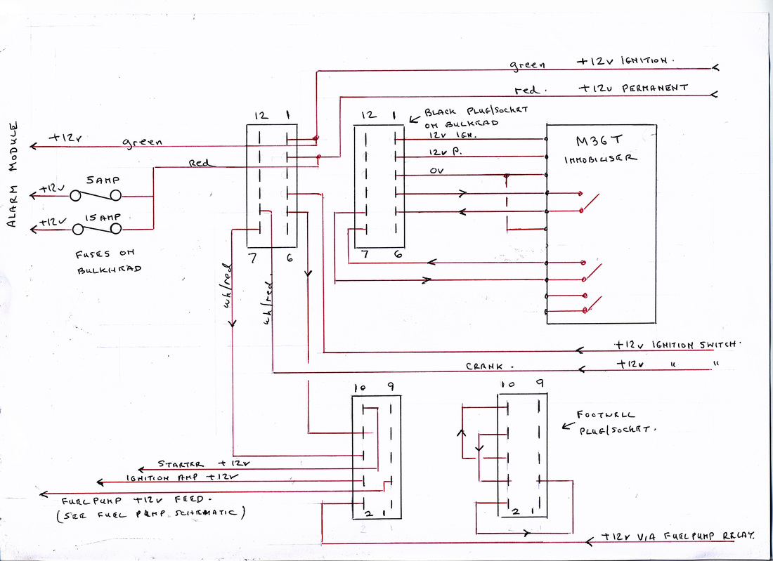
The Griffith has been fitted with several different Alarm/Immobilisers over the years and faults especially in the immobiliser are not uncommon. In general only the ignition and starter motor circuits are immobilised but it is not unknown for the fuel pump also to be protected. The Meta series of alarm/immobilisers have probably been used more than any others but due to the age of the cars many of these will have now been replaced with other products. One initial shortcoming was wiring the starter motor solonoid directly through immobiliser relay contacts, as the solonoid takes a fair amount of current during cranking it tends to overload the contacts causing unreliable cranking especially with a hot engine and eventually burns out the relay contacts. David Beer devised a modification " The Hot Start Mod" that inserts a heavier duty relay between the immobiliser and the starter solonoid to overcome the problem. Several fuses are associated with the alarm/immobiliser and for the Meta system two of these are located on the bulkhead behind the dash panel. Two 7.5Amp fuses on the main relay/panel in the footwell are marked RH and LH Indicators, but if you remove both fuses the indicators work normally. They are in fact fuses for the flashing indicators when setting the alarm, two are necessary as the Meta alarm has two separate outputs. The complete schematic for the Immobilised circuits are shown below: