TVR Griffith Cooling Fans Schematic
This information has been gathered from personal experience and is believed to be accurate but there is no guarantee that this is the case. Anyone using this information does so on the understanding that its use is completely at their own risk and that no liability for errors or omissions or consequential damage to persons or possessions will be accepted by the author or his agents. Prospective users should make their own considered judgement or seek specialist advice as to the accuracy or otherwise of any statements made before using this information in anyway.
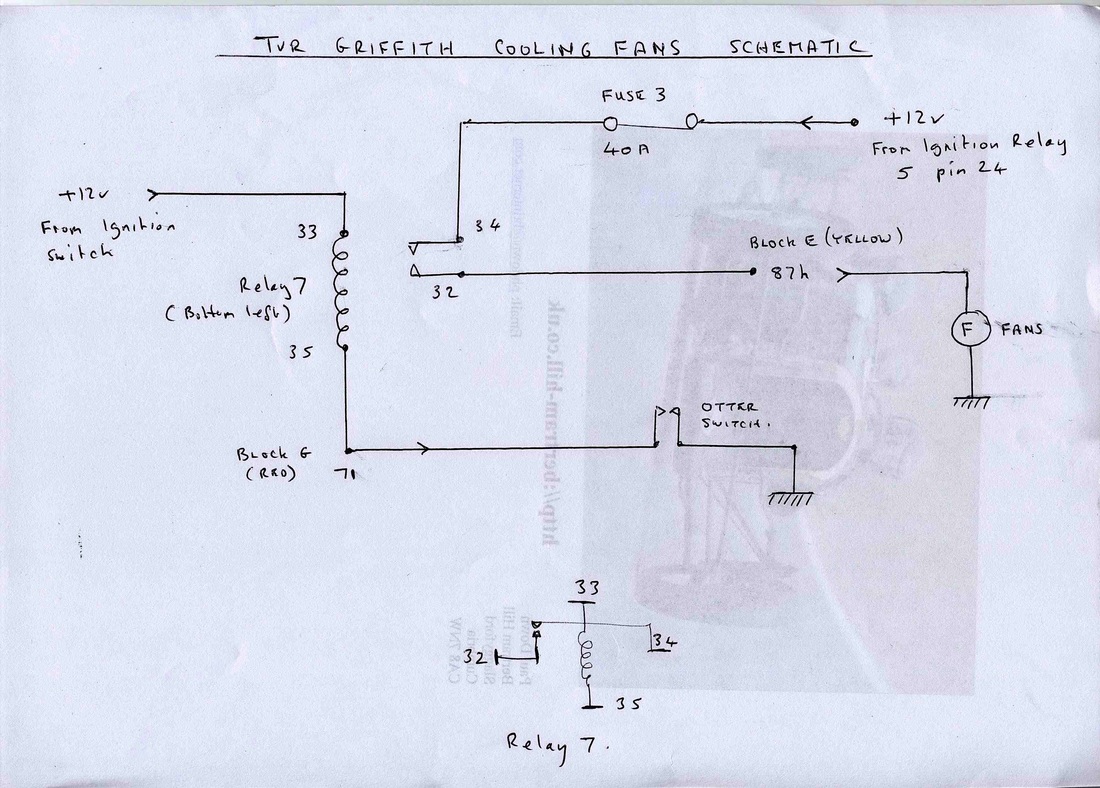
This is very rough sketch of the cooling fans circuit on a Griffith 500. This has not been traced to prove its accuracy but from information gleaned from previous traces I believe it to be substantially correct. TVR varied the layout between models so this may not represent your particular car.
The "blocks" refer to the sockets with coloured plugs at the back of the Fuse/Relay panel. They are labelled as shown, i.e. 87h, 71 etc.
Fuse 3 and Relay7 control the current to the cooling fans on my car, yours may differ but are usually indicated in the driving manual.